Contents
What is serial communication?
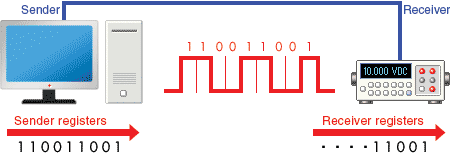
Serial communication is a communication method that uses one or two transmission
lines to send and receive data, and that data is continuously sent and received
one bit at a time.Since it allows for connections with few signal wires, one of
its merits is its ability to hold down on wiring material and relaying equipment
costs.

Serial communication standards
RS-232C/RS-422A/RS-485 are EIA (Electronic Industries Association) communication
standards.Of these communication standards, RS-232C has been widely adopted in a
variety of applications, and it is even standard equipment on computers and is often
used to connect modems and mice.Sensors and actuators also contain these interfaces,
many of which can be controlled via serial communication.
RS-232C
This serial communication standard is widely used and is often equipped on computers
as standard.It is also called "EIA-232".The purpose and timing of the signal lines
and the connectors have been defined (D-sub 25-pin or D-sub 9-pin).Currently the
standard has been revised with the addition of signal lines and is formally called
"ANSI/EIA-232-E".However, even now it is generally referred to as "RS-232C".
RS-422A
This standard fixes problems in RS-232C such as a short transmission distance and
a slow transmission speed.It is also called "EIA-422A".The purpose and timing of
the signal lines are defined, but the connectors are not.Many compatible products
primarily adopt D-sub 25-pin and D-sub 9-pin connectors.
RS-485
This standard fixes the problem of few connected devices in RS-422A.It is also called
"EIA-485".RS-485 is forward compatible standard with RS-422A.The purpose and timing
of the signal lines are defined, but the connectors are not.Many compatible products
primarily adopt D-sub 25-pin and D-sub 9-pin connectors.
|
Parameter
|
RS-232C
|
RS-422A
|
RS-485
|
|
Transmission mode
|
Simplex
|
Multi-point
simplex
|
Multi-point
multiplex
|
|
Max. connected devices
|
1 driver
1 receiver
|
1 driver
10 receivers
|
32 drivers
32 receivers
|
|
Max. transmission rate
|
20Kbps
|
10Mbps
|
10Mbps
|
|
Max. cable length
|
15m
|
1200m
|
1200m
|
|
Operation mode
|
Single-ended (unbalanced type)
|
Differential (balanced type)
|
Differential (balanced type)
|
|
Connection image
|

|

|

|
|
Features
|
Short distance
Full-duplex
1:1 connection
|
Long distance
Full-duplex, half-duplex
1:N connection
|
Long distance
Full-duplex, half-duplex
N:N connection
|
Signal assignments and connectors
In RS-232C, the connectors to use and the signal assignments have been defined and
are standardized.The figure to the right describes the D-sub 9-pin signal assignments
and signal lines.

|
Pin No.
|
Signal name
|
Description
|
|
1
|
DCD
|
Data Carrier Detect
|
Carrier detect
|
|
2
|
RxD
|
Received Data
|
Received data
|
|
3
|
TxD
|
Transmitted Data
|
Transmitted data
|
|
4
|
DTR
|
Data Terminal Ready
|
Data terminal ready
|
|
5
|
SG
|
Signal Ground
|
Signal ground or common return
|
|
6
|
DSR
|
Data Set Ready
|
Data set ready
|
|
7
|
RTS
|
Request To Send
|
Request to send
|
|
8
|
CTS
|
Clear To Send
|
Clear to send
|
|
9
|
RI
|
Ring Indicator
|
Ring indicator
|
|
CASE
|
FG
|
Frame Ground
|
Maintenance ground or earth
|
Connection method
In RS-232C, the connectors and signal assignments have been standardized, so many
standard-compliant cables are available commercially.However, equipment comes in
the following types, and depending on the equipment that will be connected, a straight
cable or a crossover cable is required.
Equipment type
DCE
Data communication equipment.This term indicates equipment that passively operates
such as modems, printers, and plotters.
DTE
Data terminal equipment.This term indicates equipment that actively operates such
as computers.
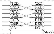
- Crossover cable connection (1)
-

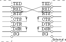
- Crossover cable connection (2)
-

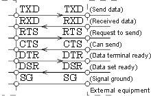
- Straight cable connection
-

Half-duplex communication and full-duplex communication
- Full-duplex communication
-
A method where send and receive both have their own transmission line so data can
be simultaneously sent and received.
- Half-duplex communication
-
A method where communication is performed using one transmission line while switching
between send and receive.For this reason, simultaneous communication cannot be performed.
Asynchronous communication and synchronous communication
In serial communication, data is sent one bit at a time using one signal line, so
in order for the receiving side to accurately receive the data, the sending side
must know at what speed it is sending each bit.In RS-232C, synchronous communication
and asynchronous communication standards have been defined.For peripheral equipment
used for measurements or control, the previously mentioned full-duplex communication
and asynchronous communication are typically used.
- Synchronous communication
-
This method sends and receives data synchronized to a clock generated by the other
equipment or by a self-generated clock.Communication is performed is based on a
synchronization signal added to each bit from the sending side.This has good data
transmission efficiency but there is a demerit in that the transmission procedure
becomes complicated.
- Asynchronous communication
-
This method sends and receives data synchronized to each side's own self-generated
clock.Normal communication is not possible if the transmission rate settings do
not match.In other words, both the sending side and the receiving side initially
agree on how many bits to transfer each second, and then each creates a synchronization
signal of a frequency that matches that transmission rate. In asynchronous communication,
data is sent and received one bit at a time on one data line, so if each side's
communication condition settings do not initially match, normal communication is
not possible.Matching the computer (controller) side settings to the peripheral
equipment side settings is the normal setup method.
- Transmission rate
-
Specifies the number of bits to send each second.The unit is bps (bits per second)
and is selected from 300, 600, 1200, 2400, 4800, 9600, 19200, and so on.By matching
the settings and timing, the data delimiters correspond, and data can be normally
sent and received.For this reason, a start bit is added to each item of data (1
byte) to acquire the correct timing.

- Stop bit length
-
This sets the length of the bit that indicates the end of the data.This is normally
selected as 1 bit, 1.5 bits, or 2 bits.The start bit length is fixed as 1 bit so
this setting is not necessary.
- Data bit length
-
This specifies how many bits each item of data is composed from.This depends on
the device being used, but normally specify 7 bits for alphanumeric characters and
symbols, and specify 8 bits for 1 byte binary data.
- Parity check setting
-
This is a function to find errors in the data and is selected from "even parity
check (EVEN)", "odd parity check (ODD)", or "no parity check (NONE)".
- Parity check details
-
On the sending side, a parity bit of "1" or "0" is added to the data so as to make
the number of "1" data bits even for EVEN and odd for ODD.On the receiving side,
the number of "1" data bits is counted and the data is judged as being correct if
the number is even when EVEN and odd when ODD.

- Handshake (flow control)
-
When sending and receiving data between devices, data may be lost when data is sent
when the receiving side is not in the receiving state, so it is important in communication
to check the other side's state.The handshake (flow control) is a function that
maintains the reliability of communications. A signal is sent from the sending side
to the receiving side that states, "data is being sent", and the receiving side
receives that signal and reads the data from the signal line.Then it sends a reply
to the sending side that states, "the data was received".In other words, data can
be transferred while each side checks the sending and receiving of data.
- Software handshake (XON/XOFF flow control)
-
This is a control method where the "XOFF code" is sent to the sending side to request
that sending be temporarily interrupted when the remaining free space in the receive
buffer gets low on the receiving side.When there is a sufficient amount of free
space, the "XON code" is sent to request that the sending side restart sending.
- Hardware handshake
-
The control lines (RTS or DTR) are automatically turned on or off as an alternative
to sending the XON/XOFF codes in software flow control.The RTS signal and the CTS
signal or the DTR signal and the DSR signal must be connected to each other.